

A type of bearing used in automobiles, generally used for automotive camshafts (shafts that control the opening and closing of piston engine valves)
Structural characteristics
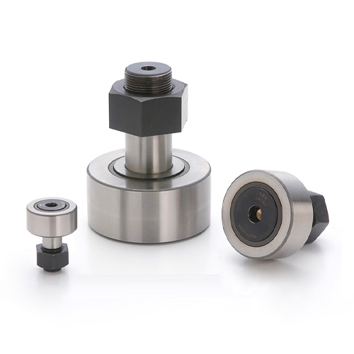
1. Combination structure of thick outer ring needle roller bearing and bolt
2. Sizes available in metric and imperial series
3. There is a lubricating oil passage inside the bolts of the bearing
4. For ease of installation, the large end of the bearing is designed with "straight" and "hexagonal hole" wrench assembly methods
5. The outer surface of the outer ring has cylindrical and spherical shapes, which can be selected according to practical applications
6. The full roller type is suitable for situations with high loads and low rotational speeds
7. Eccentric type can easily and accurately adjust the axis position of bolts when installing bearings
Bearing series
Type and structural characteristics
CFxx Standard
CFxxF stainless steel type
CFESxx solid eccentric bolt type
CFExx eccentric type
Metric Series CFxxW thrust disc type
CFxxRUI concentrated lubrication spherical outer ring
CFxxFUI concentrated lubrication cylindrical outer ring
CFxxSFU simple assembly type
NUCFxx Heavy Industry Type
CFSxx Small
English CRxx-x standard type
CRHxx x Heavy Industry Type
suffix
Structural features IKO INA SKF FAG
Retainer type - - - -
Full roller type V V V V
Attached hexagonal hole B SK SK -
Sealed UU PP PP 2RS
Spherical outer ring R - - -
Stainless steel F - - -
Thrust disc type W - - -
Cylindrical outer ring - × × DZ
Interchangeability of bearings
IKO INA SKF FAG Remarks
CF... KR... X KR... KR... D with retainer standard type
CF... R KR... KR... KR... with retainer spherical outer ring type
CF... V KRV... X KRV... - Full Roller Standard Type
CF...VR KRV... KRV... - Full Roller Spherical Outer Ring Type
CFE... KRE... X - - eccentric standard type with retainer
CFE... R KRE... - - eccentric spherical outer ring type with retainer
CFE... V KRVE... X - - Full Roller Eccentric Standard Type
CFE... E KRVE - - full roller eccentric spherical outer ring type
CR... CFC... - - English standard with retainer
CR... R CFC... Y - - Inch system with retainer spherical outer ring type
Maintenance of camshaft
(1) Check the curvature of the camshaft. Using the journal at both ends as the fulcrum, the radial runout should not exceed 0.03mm. When it exceeds 0.10mm, the cold pressing correction method can be used for correction.
(2) When the lift of the cam is not less than 5% of the specified value, it is allowed not to grind the cam, but the radial runout tolerance of the cam base circle and the cam base circle to the camshaft axis should be checked; The overhaul standard is
0.03mm, overhaul is allowed to be no greater than O.05mm.
(3) The surface of the cam should be polished for roughness, damage, and pitting. When the wear of the cam tip exceeds 1.00mm, it should be repaired after welding to restore its original size and shape,
Or replace it.
(4) If the oil pump drive gear on the camshaft has rough or worn tooth surfaces exceeding 0.50mm, it should be repaired. Individual teeth of the gear are damaged, and it is allowed to
Grind off sharp corners and continue to use. The surface roughness of the eccentric wheel driving the oil delivery pump shall not exceed O.80 μ m。 When the wear of the eccentric wheel exceeds 2.00mm, the camshaft should be repaired by welding or replaced.
(5) Cylindricity tolerance of each camshaft journal: overhaul standard is 5 μ m. Overhaul allows no more than 15 μ m. The usage limit is 25 μ m。
(6) The radial runout tolerance of the camshaft journal for timing gear installation and the end face runout error of the axial thrust end face shall not exceed 35 μ m。
Adjustment of camshaft axial clearance
The axial clearance of the camshaft should comply with relevant regulations, and the inspection method is shown in the attached figure. Use a thickness gauge to measure, or directly measure the thickness difference between the thrust flange and the spacer. When the thrust flange is worn, the shaft
When the clearance exceeds the specified value, the standard thickness of the thrust flange should be replaced, and the thickness of the spacer ring should not be arbitrarily reduced. Otherwise, it will change the axial position of the cam and affect the accuracy of the valve timing.