

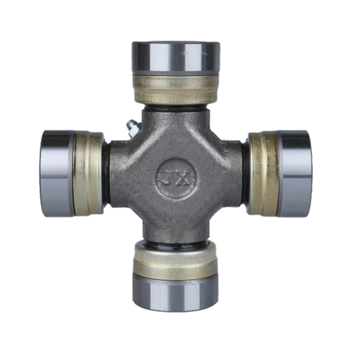
Universal joint bearing, also known as ten-byte, universal joint, the English name universal joint, refers to the mechanical structure that uses the ball connection to realize the power transmission of different shafts, which is a very important component of automobile bearings. The universal joint is combined with the drive shaft and is called a universal joint transmission. It is a mechanism for achieving variable-angle power transmission for the position where the direction of the drive shaft needs to be changed. It is the "joint" component of the universal transmission of the vehicle drive system. The cross-shaft rigid universal joint is a unequal-speed universal joint widely used in automobiles, allowing the maximum angle of intersection of two adjacent shafts to be 15 ゚ to 20 ゚. The cross shaft is one of the key components of the cross-axis rigid joint.
Classification of universal joint bearings: constant velocity universal thrust ball bearing joints, constant velocity universal joints, ball cage universal joints, three pin shaft type universal bearing joints, double factory joint universal joints, etc.
definition
The front-engine front-wheel drive vehicle omits the drive shaft, and the universal joint is mounted between the front axle axle and the wheel that are both responsible for driving and steering. In a front-engine rear-wheel drive vehicle, the universal joint transmission is mounted between the transmission output shaft and the transaxle final drive input shaft.
Introduction
In automotive drive trains and other systems, in order to achieve power transfer between the shafts where the axes intersect or the relative position changes frequently, a universal joint must be used. 2-drive shaft. The universal joint transmission generally consists of a universal joint and a rolling mill bearing drive shaft, and sometimes has an intermediate support, which is mainly used in the following positions. 1- Universal joint. 3- front drive shaft. 4-Intermediate full complement roller bearings support the transmission between the transmission and the transaxle of the engine front and rear wheel drive vehicles. When the distance between the transmission and the drive joint bearing bridge is long, the drive shaft should be divided into two sections or even multiple sections, and an intermediate support should be added. Due to the deformation of the frame, it is caused between the two transmission members whose positions are mutually changed between the axes. Between the transfer case of the multi-shaft driven vehicle and the drive axle or between the drive axle and the drive axle is between the engine and the transmission. Between the car with the independent suspension and the differential self-aligning ball bearing. The power output of the vehicle between the differential and the wheel of the steering drive axle is mounted in a linear motion bearing and steering mechanism.
Cause and treatment
The failure of the drive shaft universal joint is mainly due to the wear of the journal and the bearing and the bending deformation of each journal, so that the center line of each axis of the cross shaft is not on the same plane, or the adjacent two-axis center lines are not perpendicular. Due to the excessive wear clearance of the universal joint cross shaft journal and the bearing, the cross shaft sways during operation, causing the center line of the transmission shaft to deviate from its rotation center line, causing the transmission shaft to vibrate and the abnormal sound of the transmission shaft during operation. phenomenon. Wear is mainly caused by lack of lubrication.
The wear of the universal joint cross shaft journal and bearing should not exceed 0.02~0.13mm from the use condition, and is generally maintained at about 0.01mm. If it exceeds 0.13 mm, the transmission shaft will vibrate and sing. If the cross shaft journal wears out of the groove, the groove is deep and should be repaired or replaced. If surfacing and insert repairs are used, heat treatment and grinding are also required. After processing, the non-circularity of each journal is required to be 0.01 mm, and the taper cannot be large (not more than 0.01 mm in length of 20 mm). To check the perpendicularity of the adjacent two axes, be sure to be vertical. After machining and repairing, the axes of the journals should be in the same plane. When the vehicle is running, the direction of the force transmitted by the cross shaft is also the same because the directions of the torque transmission are the same. Over time, it causes the unilateral wear of the cross shaft journal. As time goes by, the side of the cross shaft will wear and increase, and the groove will be so loose that it will make a sound. It is possible to rotate the cross shaft by 90° with respect to the original position, which can extend the use time. When assembling, pay attention to the side with the grease nipple facing the drive shaft. The universal joint fork should rotate freely on the cross shaft. There should be no stagnation or axial clearance. In normal maintenance, grease should be inspected to prevent wear of the cross shaft journal and bearing due to lack of grease.